When people say “ESP32” they almost always mean this one: the 2016 chip with two cores and 38 pins. It still has the most tutorials, it is the cheapest board with classic Bluetooth, and even though there are more modern options, it still makes a lot of sense in 2026.
But it has a few corners —pins you cannot use, an ADC that is not as nice as the marketing suggests— that you should know before soldering anything. I have wasted more than one afternoon by not knowing them, so let’s save you the trouble.
The chip: not every “ESP32” is the same
Inside the module there is a specific chip, and they are not all equal:
| Chip | What is special about it |
|---|---|
| ESP32-D0WDQ6 | The original, 2 cores, QFN 6×6 mm |
| ESP32-D0WD | Same but in a 5×5 mm package |
| ESP32-D0WD-V3 | The current revision, used in new modules |
| ESP32-D0WDR2 | With 2 MB of PSRAM inside the chip itself |
| ESP32-S0WD | Single core (rare to see) |
For our purposes: 2 × Xtensa LX6 cores at 240 MHz, 520 KB of SRAM and 448 KB of ROM. That is the “classic ESP32”.
The modules: WROOM, WROVER and friends
The bare chip is not something you solder by hand. It lives inside a module with the flash, the crystal and the antenna. The ones you will find:
- ESP32-WROOM-32E — the standard. 4 MB of flash, PCB antenna. Leaves GPIO16 and GPIO17 free.
- ESP32-WROVER-E — same, but with 8 MB of PSRAM on top. Note: the PSRAM eats GPIO16 and GPIO17, so if you need those pins, you cannot use WROVER.
- ESP32-WROOM-32UE / WROVER-IE — no PCB antenna, with a U.FL connector for an external antenna. The fix when the ESP32 lives inside a metal box.
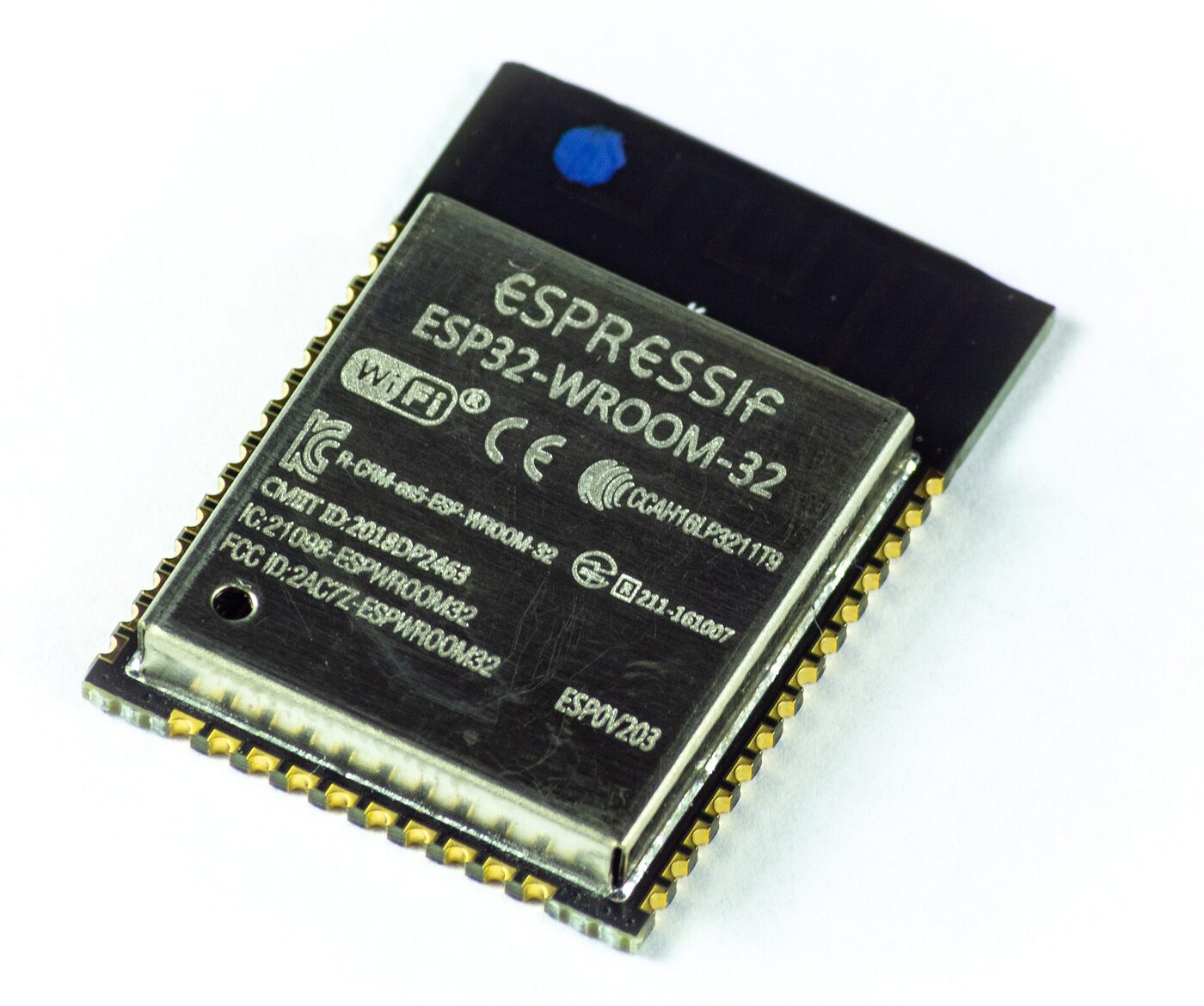
2026 note: for new designs, Espressif recommends the E series (ESP32-WROOM-32E / WROVER-E). The older modules without the “E” are marked as not recommended for new designs.
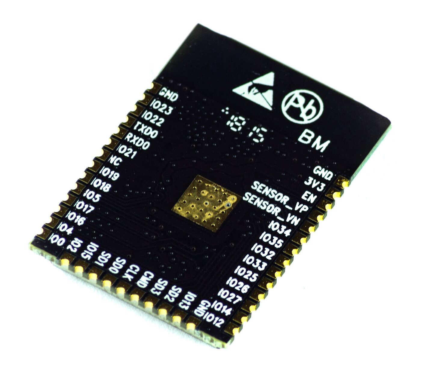
And on the back you can see where everything is:
The board you will buy
The module is mounted on a development board (devkit) that adds USB, a
regulator and two buttons: EN (reset) and BOOT (for flashing). The classic
one is the ESP32-DevKitC.
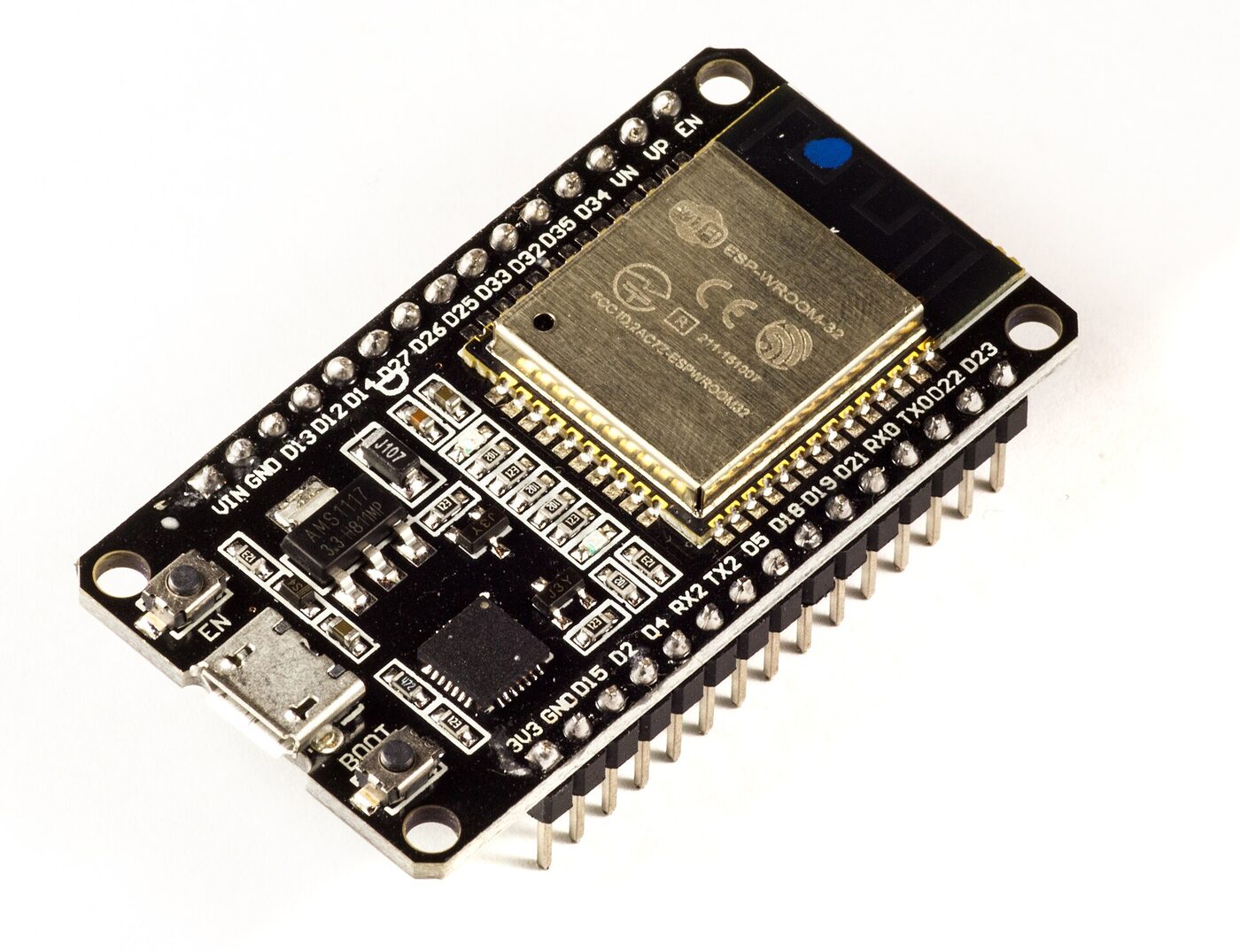
A warning worth money: these boards have no native USB. The port is a bridge chip (CP2102 or CH340) that talks to the ESP32 over UART. If you have trouble flashing, it is almost always that chip’s driver, not the ESP32.
Specs, no fluff
| Thing | Value |
|---|---|
| Cores | 2 × Xtensa LX6 @ up to 240 MHz |
| SRAM | 520 KB |
| Wi-Fi | 802.11 b/g/n (2.4 GHz) |
| Bluetooth | 4.2 classic (BR/EDR) + BLE |
| GPIOs | 34 total, ~25 usable |
| ADC | 18 channels, 12-bit (ADC1 + ADC2) |
| DAC | 2 channels, 8-bit |
| Touch | 10 capacitive pins |
| Peripherals | 3×UART, 2×I2C, SPI, 2×I2S, CAN (TWAI), SD/MMC, PWM, RMT |
The classic Bluetooth bit is unique to the classic: neither the S2, nor the C3, nor the S3 have it. If your project talks to a speaker or an old-school Bluetooth gamepad, this is your chip.
The 38-pin pinout
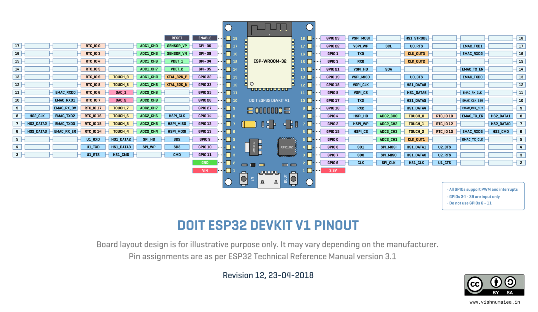
If you come from Arduino, here is a mindset shift: not every pin does everything. There are input-only pins, pins that decide how the chip boots, and pins that are literally taken internally. Let’s go one by one.
The pins that rock
The DAC (GPIO25 and GPIO26)
The classic has two real analog outputs (8-bit). The C3, for example, has none. You can output an actual voltage, generate a waveform or build a mediocre but fun synthesizer.
Touch: 10 pins that sense your finger
With no extra sensor, the chip measures the capacitance of GPIO0, 2, 4, 12, 13, 14, 15, 27, 32 and 33. Perfect for buttons with no moving parts. (This peripheral disappeared in the S2 and S3, so if you need it, you go back to the classic.)
ADC1: the one that works with Wi-Fi
GPIO32 to GPIO39 are ADC1. They are the only ones you can use while Wi-Fi is on. Burn this into your memory, because it is the number one cause of “my sensor reads random values”.
And a few lesser-known extras
- Internal Hall sensor, using no pin at all.
- Internal temperature sensor (not very accurate, but it exists).
- CAN (TWAI) in hardware, no external module.
The pins that will ruin your day
GPIO6 to GPIO11: the flash
They are wired to the flash memory. Never use them. If you touch them, the ESP32 stops booting and looks dead. It is not dead: re-flash it and breathe.
The boot (strapping) pins
On power-up, the chip looks at these pins to decide how to boot:
| Pin | What happens if it is wrong |
|---|---|
| GPIO0 | LOW enters flash mode; as an output it can block boot |
| GPIO2 | Must be LOW or floating at boot |
| GPIO12 | If it is HIGH at boot, bad news (it is about flash voltage) |
| GPIO15 | Must be HIGH; otherwise the boot log is silenced |
Rule of thumb: do not put anything critical on those pins and, if you do, check their state at boot.
GPIO34 to GPIO39: input only
They have no internal pull-up or pull-down and cannot be used as outputs. They are perfect for a sensor you only need to read, but if you try to light an LED with them it will not work and you will spend a while thinking the LED is broken.
The ADC lies (and how to tame it)
This is the detail that frustrates people most. The ESP32’s ADC is 12-bit, but:
- It is not linear. It deviates a lot near 0 V and near 3.3 V.
- It has an offset. With 11 dB attenuation it saturates earlier than the datasheet suggests.
- It needs calibration. ESP-IDF ships an eFuse calibration API. Use it.
- ADC2 does not work with Wi-Fi on. We repeat: use ADC1.
If you need decent, stable measurements, an external ADS1115 over I2C will save you a lot of headaches.
PSRAM: when you need it
PSRAM is extra memory (typically 8 MB on the WROVER). You need it if you are going to hold large buffers: images, audio, huge JSONs or network buffers.
If your project is sensors and a couple of LEDs, you do not need it and the WROOM is cheaper. And remember the toll: PSRAM uses GPIO16 and GPIO17.
When to pick the classic (and when not to)
Yes, pick the classic if…
- You need classic Bluetooth (not just BLE).
- You want DAC, touch or CAN without adding anything.
- You need lots of GPIOs and GPIO16/17 free.
- You are following a tutorial that assumes the classic and do not want to fight different pins.
Pick something else if…
- You want the cheapest, most modern option: a C3 does almost the same for less.
- You need native USB (HID, JTAG): S2, S3, C3 or C6.
- You need camera, audio or AI: ESP32-S3.
- You want Matter/Thread/Zigbee: C6 or H2.
Current tools (2026)
If you are going to program it, these are the living versions today:
| Tool | Current version |
|---|---|
| ESP-IDF | 6.1 |
| Arduino core | 3.3.11 (on ESP-IDF 5.5.5) |
PlatformIO (platform-espressif32) | 7.1.3 |
| MicroPython | 1.29 |
esp-hal (Rust) | 1.2.0 |
Typical mistakes with the classic
- Trying to use GPIO6–11 “because they look free on the drawing”.
- Putting an LED on GPIO34–39 and not understanding why it stays dark.
- Reading a potentiometer on ADC2 and getting wild values once Wi-Fi comes up.
- Using GPIO12 as an output and having the board boot whenever it feels like it.
- Buying a WROVER to use GPIO16/17 and discovering they are taken.
- Blaming your code when the problem is the CH340 driver.
Summary
- The classic ESP32 is 2 × LX6 cores, 520 KB SRAM, Wi-Fi 4 and classic Bluetooth + BLE.
- The modules you will see: WROOM-32E (no PSRAM) and WROVER-E (with PSRAM that eats GPIO16/17).
- It has unique things: DAC, touch, CAN and classic Bluetooth.
- Watch out for GPIO6–11, the strapping pins (0, 2, 12, 15) and GPIO34–39 (input only).
- ADC2 does not work with Wi-Fi; use ADC1 and, if you need precision, an ADS1115.
Next step: if you want something smaller, cheaper and with native USB, Part 3 is about the ESP32-S2. And if you do not have a board yet, start with Part 1: what the ESP32 is and its family.
Image credits
Photos from Wikimedia Commons:
- ESP32-WROOM-32 module (front and back) and ESP32-DevKitC — Ubahnverleih (CC0)
- ESP32 DevKitC pinout — Vishnu Maiea (CC BY-SA 4.0)